Alumaroom Installation Instructions
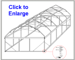
"It's like a Giant Erector Set!"
The installation instructions were in the process of being edited to include many photos and detailed diagrams of the assembly process and to define the improvements we'd made to our product when it was discontinued. As such, the new version was never finished. However, we have detailed instructions for similar products including: Ameri-Dome instructions, Ameri-Brand Patio and Spa Rooms Instructions, and Sundome Instructions.
Alumaroom Prototype Instructions
Both the Alumaroom and the prototyoe unit seen below have been discontinued. As such, we post these instructions solely as reference for DIY handymen. These instructions come without warranty & technical support. By chosing to use these instructions for your own project you agree to release from liability and hold blameless Ameri-Brand Products Inc., its affiliates and employees. That being said, enjoy and good luck.
PLEASE READ THIS ENTIRE SET OF INSTRUCTIONS
PRIOR TO BEGINNING YOUR INSTALLATION
Tools you will need:
|
If installing on a concrete surface, please allow 30 days for newly poured concrete to properly set and you will need to use a "hammer-drill" or "roto-hammer" along with 2 half inch diameter masonry bits. Do not install anchors in concrete within 6" of the edge of the slab in order to prevent "blow-out".
Laying Out the Room:
Strike a chalk line to the exact size of your
screen enclosure on the surface area where the room is to be mounted. A
level surface is best. It is a good idea to extend your lines out past
intersecting points as this will save you some extra measuring time later
and will allow you to visually see how things are lining up.
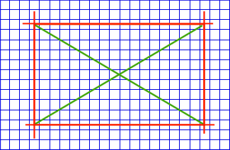
To check "square", measure diagonally from
corner to corner as shown by the green line above.
When the 2 measure the same you will have
a perfectly squared area.
Setting the Stanchions:
The stanchions or feet, will sit partially on the chalk line. It is necessary that the round portion of the stanchions are just inside or "flush" with the "inside edge" of the chalk line. A portion of the stanchions base will sit directly on top of the chalk line and will overhang out of the dimensions of your screen room as shown below.
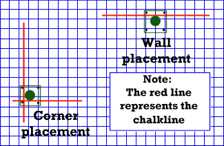
The green "filled in" circles (representing the tube recepticles) above are set right on the inside edge of the red chalk line.
Place the stanchion at the proper location,
mark the 4 holes onto the deck, remove the stanchion and drill the 4 holes.
Insert the concrete anchors and set them in pace with the punch provided.
Secure the stanchion in place with 4 bolts
and fender washers on each one. Be sure to tighten the bolts securely.
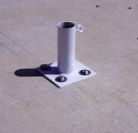
For wooden decks, use the same directions
but substitute the concrete anchors with bolts of the proper length for
your deck surface. On wood decks it is recommended that a backing plate
made of either wood or pre-drilled steel is used as extra support on the
underside of the deck surface. Be sure to tighten the bolts securely.
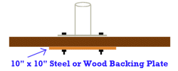
The backing plate shown above (used on wooden
decks) is to prevent the stanchion from being secured only to a single
board and spreads out the strain placed on the deck.
The wall stanchions need to be set ON CENTER at 10' intervals depending on the room you ordered. Place them in the proper location and drill, then secure according to the directions above for either concrete or wood deck installation. We will set the stanchions for the entry/end supports later, after the walls and the rest of the framework is installed in place.
Fitting Descriptions:
In the diagram below, locate the following fittings:
1. 2 Front & Rear Ridge ends.
2. 4 Corner fittings.
3. Rafter to Eave fittings. (quantity varies
depending on size of room and upright spacings.)
4. Rafter to Center ridge fittings. (quantity
varies depending on size of room and upright spacings.)
5. "T" fittings for entries and end wall supports.(quantity
of 4 standard application)
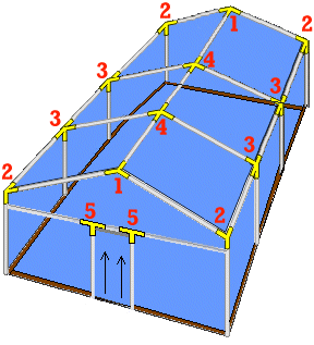
Tubing Descriptions:
In the diagram below, locate the following poles:
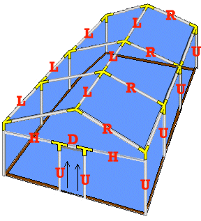
U. All uprights needed for walls. Note: The uprights which are located on the front and rear of the structure that fit into the "T"'s may need to be cut down a couple of inches in order to fit in more easily.
R. Rafters. these will be the longest poles on your unit.
L. There will be 3 "L" poles for each 8 or 10 ft. section of your enclosure. 2 on each side form the eaves and 1 at the very top is the ridge.
Please Note:
As the construction project begins, the unit may appear a bit unstable. As more fittings are secured and poles added, the structure becomes sturdier and sturdier. Each screw and piece of metal that you add to it reinforces the entire assembly. After you have placed a few of the uprights in their stanchions and secure the poles in place, you will see that the structure is well on its way to becoming a solid unit.
Assembly of the Arches:
To assemble the first "end" wall, lay the appropriate pieces out on a flat non-marring surface. This will include 4 uprights (Part# U), 2 "T"'s (Part# 5) , 2 rafters (Part# R), 2 corner fittings (Part# 2) and 1front/rear ridge end (Part# 1). You will also need 2 horizontal end support poles (Part# H) and a door/endwall support pole (Part# D). The "D" pole will be slightly less than 4' in length.
DO NOT ATTEMPT TO LIFT THE UNIT UNTIL ALL SET SCREWS ARE INSTALLED ON THE ASSEMBLY!
Use the thumb-screws provided on the fittings
to hold the assembly in place while you measure and set the poles to the
proper dimensions while it is laying flat on the ground. Double check your
"outside" measurements (according to the room size you ordered) as shown
in the diagram below to assure that you have the end wall dimensions set
properly.
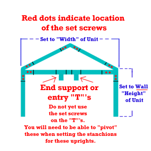
When you are confident that the room width
and wall heights are correct, pre-drill 1/8" pilot holes at each location
where you will be placing the hex head set screws. Use the hole spacing
shown in the picture below as a guide. NOTE: PLACE
ALL
SET SCREWS IN SUCH A POSITION THAT THEY WILL NOT COME IN CONTACT WITH
THE OUTER COVERING OF YOUR STRUCTURE.
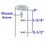
Screw in 2 set screws at each location as
shown in the diagram above. Do Not yet place set screws on the "T"'s
as you will need to "pivot" them into place at a later time.
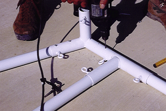
Use a rag to rub the tubing and fittings to
check for any "Burrs" or slivers. These may snag the outside material of
your enclosure. With a file smooth out the "Burrs" and recheck
for snags.
Lift the unit up and position it directly next
to the stanchions into which it will be placed. Be sure the set screws
are facing into the room. Lift straight up and slide the assembly into
the bolted down stanchions. It will stand by itself at this point, but
don't place any excessive lateral pressure on it yet.

Assemble and position the remaining interior
arches and the end arch of the structure. .
Placing the Eave & Ridge Tubes:
It's now time to place the horizontal tubes in place. A bit of information to keep foremost in your mind: The enclosure was ordered to be a specific length. The wall coverings and roof system were made to fit the unit that was ordered. As you add the horizontal ridge and eave poles, and adjust their lengths accordingly to make the final OUTSIDE length dimension of the structure (both at ground level and overhead) equal to the room size that was manufactured. This will make for a clean and easy installation. Remember, since we're flexible on the length of the tubes (due to the depth of the fitting ends, and you will be installing 2 set screws at these points) precise measurements are not critical. If you need to cut a little bit off of a tube (to maintain length), it's not a problem as long as you cut within reason.
On each eand wall, install 2 "T's" (shown as
#5 in the "fittings" diagram located at the beginning of the instructions)
near the center of each end wall on the horizontal tubes. Temporarily hold
the "T's" in position with the thumbscrews. These need to be set at 48"
ON CENTER. If you're installing a Doorway on the long side (eave side)
you will position a single "T" which is used as a side jam of the entry.
The other side of Doorway (jam) will be one of the main posts. These need
to be set at 48" ON CENTER.
Start by installing both eave poles (L) in
place at each section. Check your measurements at the ground level from
the corresponding stanchions. Use the thumb screws on the fittings on the
eave pole to set proper distance. Once confirmed, pre-drill and secure
with 2 set screws at each intersecting point. These screws should be drilled
and screwed from the bottom of the fitting to keep the final covering from
snagging on it. Keep in mind that if working over water, use the battery
operated drill and the towel to catch any metal particles preventing them
from entering the pool. Install the ridge in the same manner. Continue
checking for "burrs" on the structure with each piece you install.
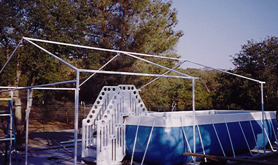
Continue the process with each section until
all poles are installed on the eaves and the ridge. You will want to confirm
that the overall length is correct. If you are off, double check
your measurements and adjust as needed before you set the final set screws.
You will notice that by this time the structure is becoming very stout
and we have not yet set the verticals with set screws into the stanchions!
We will install the final set screws into the base stanchions prior to
hanging the wall panels as some wall height adjustment will be needed at
that time.
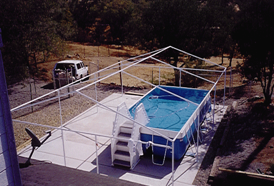
Double check your squareness of the room structure.
Also, double check to be sure that each overhead tube and corresponding
fitting is secured together with 2 set screws at each juncture where all
tubes slide into the fittings. DO NOT YET SET THE SCREWS INTO THE BASE
UNITS ON THE CONCRETE DECK.
Setting End Supports & Entry:
Establishing the Doorway Opening and Mid-span support at End Walls (standard)
Begin on the short wall without the entry. The entry size on all units is 4'-0" ON CENTER as shown below.
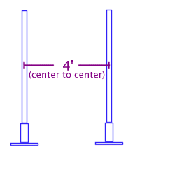
Measure the correct distance (4') and temporarily set the thumb screws securing the "T"s to the horizontal tube. The outside edge of the round receiving tube on the stanchion should sit on or very close to the original chalk line you set earlier on the deck. Take an upright and slip it fully into a loose stanchion. Set the thumb-screw on the stanchion to hold the tube in place. Tilt the "T" at an angle and fully insert the end of the upright tube into the "T" as shown below. (If the upright is too long, remove it and cut off an inch off its length.) Lock down upper end of Upright tube into the "T" with the thumb-screw.
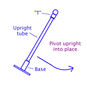
Pivot the assembly into place and double check to see if you are centered (horizontally) on the wall at both top and bottom of the upright. This can be done by measuring from both ends of the wall to the uprights. You can "eyeball" the tubes to see if they conform with the alignment of the 2 corner posts by looking down the wall. Adjust as needed before bolting the stanchions in place. Secure the "T's" to the horizontal rail with 2 set screws each side and to the top of the uprights. DO NOT YET USE THE SET SCREWS TO SECURE THE UPRIGHT TUBE TO THE BASE STANCHION.
Repeat process for all end wall uprights that are joined with "T"'s.
Placing the Perimeter Base:
It's now time to cut and mount the 2" x 4" perimeter base to your deck surface. The use of Redwood or Pressure Treated wood is recommended. You may want to stain or paint the wood ( be sure to cover all sides and ends) in a complimentary color for a better appearance. If you decide to stain and seal redwood you will probably want to use a clear spar varnish as it will not harm the vinyl components of the room. Consult with your local paint supplier for their recommendations for painting or staining. You will need enough lineal footage of 2" x 4" to complete the entire perimeter of your enclosure. Lengths and quantity purchased will depend on the unit you purchased plus 1 extra 2" x 4" x 8' economy grade for use as a "Jack". Placement of the wood is not necessary at the entry location. If there is a need for special access, you may want to leave that portion unfilled.
First, measure and cut each individual piece
to the appropriate length. A tight fit is preferable.
"Kerf" or cut away the excess wood on both
ends of the board as shown below.
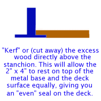
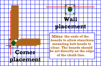
Next, miter the ends of the base wood as shown
below. This is to allow proper clearance for the bolts that secure the
stanchions to the deck surface. Measure 2" from end of 2"x4" and draw a
45 degree angle and cut. Check for fit before staining or painting. (on
the bottom side you might want to label each piece). Note:
Generally a crayon will show through a stained or painted surface.
 |
 |
 |
 |
For concrete deck installations, drill 1/2" holes in the 2x4 (1 bolt within 8" from each end and 1 in the middle).Using the drilled base-board as a template, mark the holes on the deck through the board. Remove te board and drill 1/2" dimeter holes x 2" deep into your concrete deck. Install the anchors in the holes and with the setting tool provided and tap to set and lock in the anchor into place.
For wood deck installations, use the same spacing as shown above and use 3/8" diameter bolts with fender washers and nuts to secure the base assembly boards to your deck. These bolts need to go completely through the deck for adequate structure strength. Do Not use lag screws.
Setting the Wall Height of the Structure:
Now it's time to set the wall height on the structure. Measure wall height of a wall panel. Cut the extra 2" x 4" x 8' piece of wood to this dimension. We'll call this our "wall jack". Have your drill and set screws at hand. Beginning in any corner, place the top of the "room jack" on the underside of the top rail fitting of the upright you're about to elevate. Place the bottom of the "room jack" on top of the 2" x 4" base. Tap the bottom of the "room jack" with your hammer or foot until it is vertical with the upright you are raising. While the "room jack" is in place and Pre-drill 2 holes on the inside of the stanchion (being careful not to have the screw heads located in a place where the wall fabric would be able to rub on them) this will permanently set the height of the unit. Working around the enclosure from one upright to the next, complete the same process on each one.
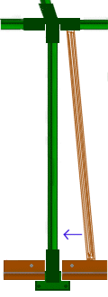
When all uprights are set in place with the screws, your room will be at proper wall height all around the perimeter. Double check to make sure all set screws are installed and all "BURRS" are removed.
Because of the possibility of variations in
deck "levelness", this system provides for that issue and with our roof
tensioning system, we will still be able to "torque" the wall panels to
help eliminate possible wrinkles.
Your framework is now set and ready to receive the roof cap and wall panels! As you can see, the unit is now very rigid and with the outer coverings yet to come, it will become even more sturdy.
Installing the Roof cap:
Note: This should be installed on a calm day. If it's windy, wait for another time when the wind is not going to be a problem.
The roof system is placed next as this allows
you to move freely between the uprights to position it without having the
wall panels to walk around. This is where the help of 2 or 3 friends comes
in handy. On a non-marring surface, unroll the roof cap and properly position
it on the deck at one of the short ends of the structure. Using the 2 step
ladders along with 2 people (one on each end of the short wall). Have the
2 helpers hoist the leading edge over the lower sections of the arch while
a third uses the pushbroom to hoist the center portion over the highest
portion of the arch. Work enough material over the top of the unit to drop
down into the first section. This will help hold it in place. Move the
ladders a few feet toward the other end of the room. Again, work the top
cap toward the opposite end of the structure. As you proceed, it gets easier
as there is less material weight to pull straight up the wall at the end
where you began the process. When the entire cap is in place, center it
as best as possible but do not yet secure it in place.
Installing the Cables:
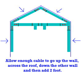
At this time you will want to install the
cable through the D-rings of the Roof Cap. Allow enough cable length as
shown below. For the time being, the cables will simply hang down the sides
of the structure. After the walls are completly installed, the cable will
then be slipped through the D-rings on the interior of the walls and then
the turnbuckles and eyes will be installed.
Attaching the Wall System:
Note: Complete one
wall panel at a time
The wall panels are designed to mount directly
below the eave rails. Upward tension is achieved via adjustable straps
(A)
that loop over the eave rail and are tightened with a non-corrosive buckle.
There are 2 of these straps for each 10' section of wall. The strap is
attached to the wall paned via a 3/4" electrical conduit tube (emt) which
is inserted into the top hem through a slit you will need to make in it.
Make any needed slits on the inside of the wall system. The straps
are threaded through oval shaped cut-outs in the top of hem. These cutouts
should be about 2" wide and 1" high. There needs to be 2 cutouts per 10'
of lineal wall length. Place your cutouts directly between an upright post
and the "D" rings that accept the interior tension cables for proper spacing
and even wall tension.
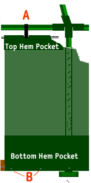
Start installing the wall panels by configuring
the top hem cutouts (A) and strap system.
Slit the inside of the top hem and insert the conduit through it. Hang
the wall panel on the eave tubes with the straps provided, leaving
them free to hang down a foot or so from the top rail.
Next, secure the base hem as described below, being sure to pull laterally as you go to help remove any wrinkles in the fabric. After the base is secured, tighten the wall panel vertically using the adjusment straps shown as (A) above. There will be an excess of strap material left after the walls are properly tensioned. When the room is fully completed, cut off the excess strapping leaving about 6" of strapping hanging on each one. Use a soldering iron (no direct flame) to "fuse" the loose ends to help prevent any fraying.
The bottom hem is secured to the base wood
by inserting a redwood lathe into the hem. The bottom hem will also need
to be "slit" on the inside to allow the redwood lathe to be inserted into
it. This keeps the bottom run of fabric uniform in appearance and makes
it easy to set in place. Screws and decorative washers (B)
are used at 12" intervals to "lock" the bottom hem in tight.

It's a good idea to cut a piece of lathe 12"
long and use it as a spacing tool when screwing in the bottom hem fastening
screws as shown below.

The ends of the walls are fitted to terminate
directly at an upright. This can be at a corner or at any other upright
on your unit. Some units will have multiple wall panels. The ends of these
panels are also fitted with a vertical hem which is designed to encase
another piece of redwood lathe. Some units require the slit to be completed
in the field during assembly. Others will have an opening already. Slide
the lathe into the vertical hem and secure with screws and washers. Overlap
the vertical hem of the next wall panel and secure directly over the first.
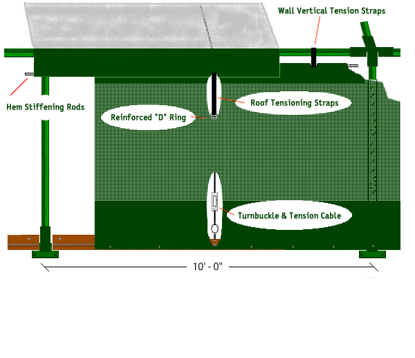
Wall & Roof Cap Diagram:
Installing your entry:
Your zipperred entry will have 2 vertical
hems (one on each side) and a hem on the top of the entry. Cut and insert
lathe into these hems and secure in place over the ends of the wall
panels.
Fitting the Tension Cables and Turnbuckles:
The turnbuckles are fitted between the uprights
and inline with the cables you have previously inserted in the roof cap.
Thread the loose cable from the roof cap through the 2 "D" rings on the
interior wall directly below where the cable hangs down. Place a mark in
the center of your 2x4 perimeter below the lowest "D" ring. Fully screw
in one of the lag eyebolts provided and attach the loose end of the cable
to the main cable with the cable clamps provided. To assure a strong cable
system, it's a good idea to loop the cable through the eyebolt Twice
and then clamp the loose end to the main cable.
Go over to the side of the room and manually pull on the cable to remove any excess slack. At this time, look to see if the cable is running straight across the top of the room in the roof and eave areas. If it is not, simply slide the cable over to the appropriate location and then once again pull out the excess slack. Mark your 2x4 base at the location where the turnbuckle will place the most direct vertical pull on the cable. Fully screw in an open-end hook at this location. Slide the eye of the turnbuckle over the openend hook and holding it upright with slight pressure, loop the loose end of the tension cable through the upward eye of the turnbuckle. Here again, loop it through Twice for added strength. Pull it as tight as possible manually to remove any slack out of the cable. Attach the loose end of the cable to the main portion of the cable with the cable connectors provided. Turn the turnbuckle a few turns to keep it a bit snug for the time being. Cut off the excess cable at this time.
Complete the same procedure for each cable assembly.
After all cable assemblies are properly attached, it is then time to tension the system. Use the turnbuckles to achieve a good solid pressure on the cables. The idea here is not to pull the eyebolts out of the wood, it is to keep the wall panels and roof cap from moving excessively in the wind. Take note that the turnbuckles can place a large amount of strain on the structure. They can actually "bow" the steel tubing if too much tension is applied. It is normal for the room to pop or creak a little as the cables are tensioned properly. The good thing is that they also help to hold the entire room very solidly in severe wind situations. After a period of time, (a few days or so) you may need to adjust the turnbuckles again as things have settled into place.
Securing the Roof Cap:
The roof cap is secured in place with adjustable
tension straps that attach to the "D" rings on the exterior of the structure.
You will find these located a foot or so from the top of the wall and inline
with the interior tension cables. Place a slit on the inside edge of the
roof cap to accept a 3/4" diameter conduit. Slide enough conduit through
the opening(s) to form a rigid profile around the roof cap perimeter. Cut
an oval opening (as you did in the top hem of the walls) into the bottom
of the perimeter hem on the roof cap at the location of one of the "D"
rings on the exterior of the wall panels.
Thread a strap through the oval opening, around
the counduit, and through the "D" ring. Fasten the buckle and pull lightly
to allow about 6 to 8 inches of free-play in the strap.
Complete the same process on the other "D" rings.
Once all roof cap straps have been properly attached, the roof can be evenly tensioned by walking around the structure and tensioning it a bit at a time. Look to be sure that the roof cap is being pulled evenly on all sides. Make any needed adjustments with the straps.
When the room is fully completed, cut off the
excess strapping leaving about 6" of strapping hanging on each one. Use
a soldering iron (no direct flame) to "fuse" the loose ends to help prevent
any fraying.
Clean Up & Go Swimming!
Notes about Your New Enclosure:
Although your room will withstand excessive heat, do not place a hot Bar-B-Que or High Heat Lighting within 3 foot of the wall system.
Also, do not leave the roof cap on without the wall system being in place. This could create a problem if there was to be a severe wind condition.
For severe snow conditions, remove both the wall and roof cap coverings. During this time, the frame can remain in place.
The zippered entries may require a spray of silicone a couple times per season to keep them operating easily.
 Inflatables Domes